Vamoose 45' John Hacker Special Commuter Laser Cut Short Kit
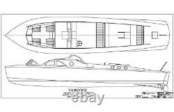
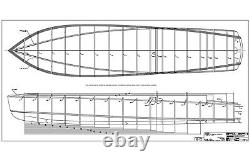
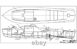
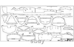


Was launched in the Spring of 1936. She was built for Charles Lyon by Fitzgerald & Lee. Lyon operated the boat through the season and decided he was not happy with the forward cockpit and the cabin. The forward cockpit was covered and described as a "Rumble Seat" that was accessed over the deck. The forward cockpit had a vee shaped glass windshield forward of the cockpit.
Lyon had Fitzgerald & Lee modify the boat to enlarge the forward cockpit by opening it up, moving the forward wall of the cabin aft, making access to the forward cockpit through the cabin and making a wooden frame vee shape windshield with glass sidelights. The exhausts were increased from one per engine to two per engine. Some items on the original build did not match the plans. The sidelights on the bridge are not the same shape as shown on the original plans. The stern treatment did not have the corner radii shown on the original plans.
The table of offsets and one sheet of the original plans show 10 stations. A second sheet of the original plans calls for 17 stations that must be interpolated from the lines generated by the 10 stations from the table of offsets.
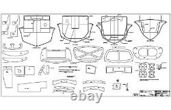
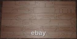
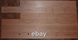
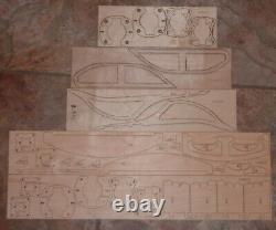
This hull was very difficult to develop to ultimately have the 17 stations. The model is scale as best as can be determined at 1 ½" = 1'-0".This is a short kit, the builder supplies all the flat wood and the hardware. The model is 68 1/8" long with a 15 3/8" beam. There are 6 sheets of plans. Each sheet in the set of plans is 36" X 72", sheet 6 is in color as the original blueprint plans. The CAD plans show all major parts full size.
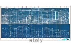
Sheet 6 has the original interior elevation and deck plan at the 1 ½" = 1'-0" scale of the model. The original blueprints for the boat were drawn at 1" = 1'-0". Sheet 6 provides a lot of information for finishing the interior of the boat and the deck hardware type and location. The stem/keel and the stations are ¼ Basswood.
The deck beams, stringers, fore and aft cabin walls are ¼ Basswood. The sheer and chines are best made from multiple strips of 1/8 x ¼. The sheer is not flat on the top side. The stations have standoffs to allow the hull to be built upside down on a flat surface. The boat had twin engines, the model is set-up for twin Leopard 4074 X2 motors.
The motor mounting system allows the motors to be installed or removed from the boat by removing 6 easily accessed #4 socket head cap screws for each motor without disturbing the motor to shaft alignment. The mounting system allows adjustment of the motor position up and down and/or port and starboard independent of the motor attachment. The MM4 motor mount bases are to be assembled as a left hand and right hand. The motor mount assemblies are to be assembled/laminated with epoxy. The MM4 motor mount bases are to be epoxied to the S12 frame.
Make sure the MM4 motor mount bases are fully seated downward on the S12 frame before they are epoxied in place. Tighten the MM3 assemblies to the MM4 bases before the epoxy is applied to hold the bases to the boat. DO NOT TRY to use 5 minute epoxy for these assemblies or the attachment to the hull. The engine room roof is a separate assembly that fits the engine room like a box lid. It should be retained by a couple of magnets.The excellent book Wooden Boats of the St. Lawrence River by David Kunz and Bill Simpson has a lot of history and photographs of Vamoose. If you are building the model the book will supply a lot of information about the boat.


